DOS 525 - Week 4 Discussion
Writing Prompt
Initial Post: The New York System of Brachytherapy Planning
When planning intracavitary brachytherapy, it is important to establish a system of geometry with respect to the patient's anatomy so that dose can be properly tailored to achieve therapeutic coverage. There are many systems in use, and a common thread between them includes finding points in space based of of fixed distances and directions from landmarks found in the anatomy or the applicator apparatus.1 These points are chosen to stand in as proxies for particular pieces of anatomy that are presumed to be in that vicinity. Some anatomic landmarks are relatively easy to see based on adjacent proxies such as catheter balloons or radiopaque packing, but many of the landmarks such as lymph node groups are difficult to locate on imaging. Manual attempts to find these difficult structures could result in error that would be dangerous when it is used to define the prescription of high local doses. A standard system of measurement, even if it doesn't line up perfectly, typically provides a reasonable substitute and provides more consistency in planning.
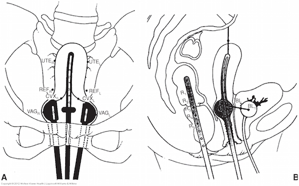
The New York System is one system among many that creates a set of standardized reference points. This system is meant to be used with a specific type of apparatus; the Henschke applicator. The reference points used in the New York System are:
Vaginal points:
- VG1R and VG1L, at the lateral surface of the ovoids (shown as VAGR and VAGL on Figure 1A)
- VG2R and VG2L, at 0.5 cm depth (not shown on Figure 1A)
Cervix points:
- CVXR and CVXL, 1 cm superior of the cervical os, then 1 cm lateral to each side (Figure 1A)
Reference points for comparison to other systems:
- REFR and REFL, 2 cm superior to the cervical os, then 2 cm lateral to each side, much like the "A" points in the Manchester system (Figure 1A)
- OBTR and OBTL, close to the obturator nodes and similar to the "B" points in the Manchester system (not shown on Figure 1A)
Uterus points:
- UTER and UTEL, 1 cm inferior to the tandem tip, then 2 cm lateral to each side (Figure 1A)
Bladder points:
- BL1 at the center of the Foley catheter balloon (Figure 1B)
- BL2 on the surface of the Foley balloon at the point of nearest approach to the cervical os (Figure 1B)
Rectum points:
- R1-R5 are points along a rectal marker marker device that control dose along the length of the rectum (Figure 1B)

Figure 1. Reference points used in the New York System
This is a rather complex system, but the calculation of dose can be performed by a computer. The first systems developed did not have this luxury, as they were developed as far back as the 1920s to 1940s and had to be simple enough that a human could calculate them in a reasonable amount of time. Once the points are localized, either a human or a computerized planning system can develop a plan to deliver an appropriate dose coverage that meets dose specifications for all points.
Grayden, Chicago
- Khan FM, Gerbi BJ. Treatment Planning in Radiation Oncology. 3rd ed. Philadelphia, PA: Lippincott Williams & Wilkins; 2011:316-324.
|
Academic Courses > DOS 525 > The New York System of Brachytherapy Planning
|
Written April 29, 2015
Second Semester, 4 Months into Internship |